Introduction
In modern defense and aerospace systems, radar-based track detection plays a critical role in situational awareness and threat assessment. Using Analytical Graphics Inc. (AGI) STK DME components, developers can simulate realistic radar sensors, model target motion, and compute detections based on signal-to-noise ratio (SNR), field of view (FOV), and radar cross-section (RCS).
This post explains how we implemented track detection simulation using STK DME in C#. We’ll go through key parts of the setup—without unnecessary boilerplate—focusing on the core logic for radar initialization, FOV setup, SNR evaluation, and detection.
Use Cases
- Defense Simulation: Evaluate radar coverage, detection probability, and target visibility in complex scenarios.
- Mission Planning: Determine which targets fall inside the radar cone and how detection varies with orientation.
- Algorithm Testing: Integrate with real-time simulators (e.g., PrithviGIS or CesiumJS) to visualize dynamic tracks.
- Training & Analysis: Model sensor limitations and environmental impacts on radar detection.
Radar Simulation Setup
We begin by creating colocated transmit (TX) and receive (RX) platforms using the STK DME Platform class. Both share the same motion and orientation as the aircraft.
ownshipTx = new Platform
{
    Name = "Ownship_TX",
    LocationPoint = aircraft.LocationPoint,
    OrientationAxes = aircraft.OrientationAxes
};

ownshipRx = new Platform
{
    Name = "Ownship_RX",
    LocationPoint = aircraft.LocationPoint,
    OrientationAxes = aircraft.OrientationAxes
};
We then configure a parabolic antenna with realistic parameters such as diameter, efficiency, wavelength, and gain:
double antennaDiameter = 3.0;
double antennaEfficiency = 0.7;
double wavelength = 0.03;  // 10 GHz (X-band)
double amplifierGain = 1e6;

var parabolicGain = new ParabolicGainPattern(antennaDiameter, antennaEfficiency);
var txAmplifier = new ConstantGainAmplifier(null, amplifierGain);
var txExtension = new RadarTransmittingAntennaExtension(txAmplifier, parabolicGain);
ownshipTx.Extensions.Add(txExtension);
Defining Radar Field of View (FOV)
The radar’s field of view determines which targets are visible. Here, we use a ComplexConic shape with a configurable azimuth range and maximum detection radius.
coneFov = new ComplexConic(
    innerHalfAngle: 0.0,
    outerHalfAngle: Math.PI / 2.0,     // 90° cone
    minimumClockAngle: 30 * Math.PI / 180,
    maximumClockAngle: 50 * Math.PI / 180,
    radius: 800000.0                    // 800 km
);
ownshipTx.Extensions.Add(new FieldOfViewExtension(coneFov));
The field of view can be dynamically updated during simulation to mimic radar sweep motion:
coneFov.SetClockAngles(minAngle * Math.PI / 180, maxAngle * Math.PI / 180);
Creating SNR Evaluators for Each Track
Each simulated target (or track) is assigned an RCS (Radar Cross Section) model and linked to the radar using LinkSpeedOfLight.
The SignalToNoiseRatioScalar object computes whether the radar can detect a given target.
var forwardLink = new LinkSpeedOfLight(ownshipTx, target.Aircraft, GlobalVariabes.earth.InertialFrame);
var returnLink = new LinkSpeedOfLight(target.Aircraft, ownshipRx, GlobalVariabes.earth.InertialFrame);
propGraph.AddLink(forwardLink);
propGraph.AddLink(returnLink);

var snrScalar = new SignalToNoiseRatioScalar(
    ownshipTx,
    target.Aircraft,
    ownshipRx,
    intentStrategy,
    propGraph,
    false,
    SignalToNoiseRatioComputeMode.Integrated
);
snrEvaluators[target.Id] = snrScalar.GetEvaluator(evalGroup);
This evaluator computes the instantaneous or integrated SNR for each target based on the radar and geometry setup.
Evaluating Radar Detections
During each simulation timestep, we:
- Update simulation time.
- Check if each target lies inside the radar’s FOV.
- Evaluate SNR (if available).
- Mark the track as detected if it meets the threshold.
foreach (var t in TrackSimulator.tracks)
{
    var inFovEval = fovExtension.GetPointIsInFieldOfViewEvaluator(t.Aircraft.LocationPoint);
    bool isInFov = SafeEvaluate(inFovEval, timeToUse);
    if (!isInFov) continue;

    if (snrEvaluators.TryGetValue(t.Id, out var evaluator))
    {
        double snr = evaluator.Evaluate(timeToUse);
        double snrDb = 10.0 * Math.Log10(snr);
        if (snrDb > -90.0)   // detection threshold
            detectedTracks.Add(t);
    }
}
This approach ensures radar detections are based on both geometric visibility and signal power, providing realistic simulation fidelity.
Result and Integration
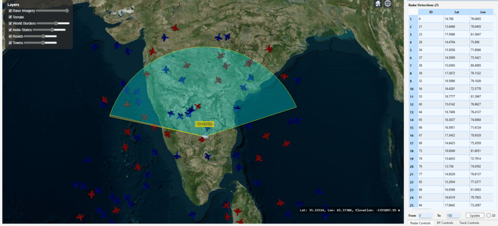
The detected tracks can be visualized in:
- PrithviGIS (QGIS-based map viewer) for 2D tactical display.
- CesiumJS frontend for 3D airspace visualization.
Detected targets are dynamically updated via WebSocket or PostgreSQL/PostGIS sync, enabling live visualization.
Conclusion
Using STK DME components, it’s possible to simulate highly realistic radar systems — complete with antenna models, signal propagation, and SNR-based detection logic.
By integrating this radar simulation module with map visualization or mission analysis tools, developers can model complex scenarios involving hundreds or thousands of aircraft tracks in real time.
At Manya Technologies, we leverage this radar detection framework in our simulation and GIS-based visualization systems, combining Qt, CesiumJS, and STK DME for defense-grade situational awareness applications.
If you’re interested in a full-fledged GIS solution, check out our flagship product PrithviGIS – a powerful QGIS-based platform for real-time geospatial visualization. PrithviGIS is an indigenous GIS development in India.
Check out our Live Aircraft Simulation using CesiumJS.